LaserGrid Anomaly Localization
Drone-Based Hazard Detection and Geospatial Localization
Project Overview
LaserGrid Anomaly Localization is an intelligent inspection system designed to identify and precisely locate hazards on airport runways, such as debris, cracks, or foreign objects.
By fusing laser line projections, aerial camera footage, and drone telemetry data, the system translates visual anomalies into accurate geographic coordinates that can be acted on by airport maintenance and safety teams.
Business & Safety Context
Manual runway inspections are time-consuming, operationally disruptive, and potentially unsafe. They rely heavily on human observation and are prone to missed hazards or inconsistent reporting.
The goal of this project was to design an automated, drone-compatible solution capable of detecting anomalies and reporting their exact location with high precision, reducing inspection time while improving accuracy and safety.
Solution Design
My role led the geospatial logic design, video and telemetry synchronization, and spatial validation. I owned the end-to-end logic that converted visual detections into actionable geographic coordinates.
The system fuses multiple data sources to localize anomalies accurately:
- Laser Linear Projections: Enhance surface feature detection.
- Aerial Video Frames: Capture visual anomalies.
- GPS & IMU Telemetry: Determine position, orientation, and heading.
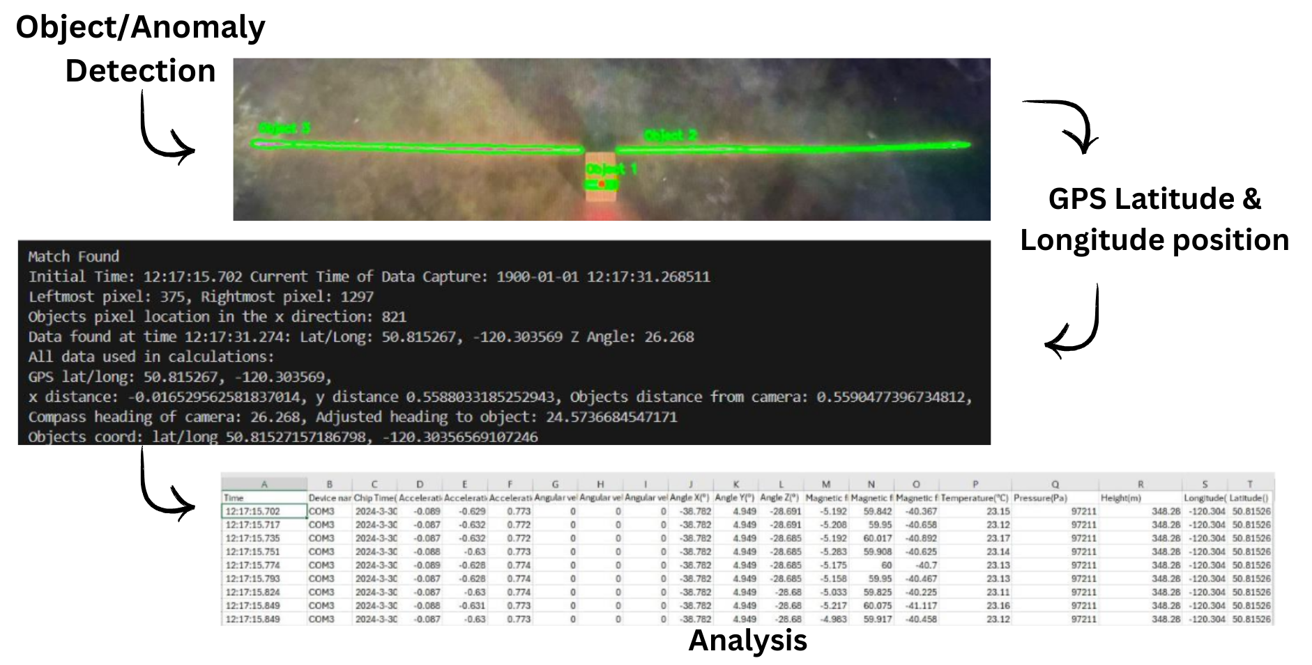
How the System Works
1. Visual Detection and Distance Estimation
Laser line projections highlight surface irregularities. Distance estimation is computed using camera field of view and laser distortion analysis, with dynamic adjustment to improve accuracy across varying surface textures.
2. Video and Telemetry Synchronization
Video frames are synchronized with GPS and IMU logs using timestamp alignment. Separate time domains are reconciled to ensure spatial accuracy between visual data and drone positioning.
3. Geospatial Conversion
Compass heading and drone orientation are converted into directional vectors. Detected anomalies are mapped from image space into GPS coordinates. Dynamic Z-angle correction is applied to account for drone stability during flight.
4. Validation and Mapping
Predicted anomaly locations are validated using ArcGIS. Outputs are mapped and reviewed against known ground truth points to verify accuracy.
Outcomes
- Sub-30cm Precision: Achieved under 30 cm geolocation error across test scenarios.
- Automated Reporting: Generated real-world anomaly reports with automated image capture.
- Improved Estimation: Demonstrated superior accuracy using field-of-view-based estimation compared to static calibration.
Challenges & Solutions
Video & GPS Synchronization: Aligned independent video and telemetry streams using timestamp-based logic to ensure spatial consistency.
Laser Distortion: Handled variable lighting and surface textures through adaptive preprocessing techniques.
Drone Stability: Applied dynamic Z-angle correction to compensate for in-flight movement and orientation changes.